

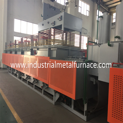
HBQ-3000-150-80 Mesh Belt Bright Annealing Furnace
1. Application
The furnace is mainly used for bright annealing treatment of metal parts.
2.Structural Introduction
The furnace is mainly comprised of preheating section,
heating section, cooling section, mesh belt, driving system,
gas pipes, water pipes, and electrical control cabinet.
To reduce gas consumption, the furnace has a bridge structure
for connecting the preheating, heating and cooling section.
There is a tilting angle of ≤80 for connection.
2.1 preheating section
Overall dimension: 2000mm(L)×350mm(W)×200(H)mm
The preheating section is comprised of muffle, furnace door, ignition
device, and fume hood. Since the muffle entrance has 80 tilting angle,
there is one large arc for smooth transition to the level part of the muffle,
which could ensure a stable, vibration-free, and sliding-free movement
of the parts. The outer surface of the preheating section is wrapped
with heat preservation cotton for preheating the parts. The movement
of the rolling wheel of the preheating section could prevent the
deformation of the muffle at the length direction.
Muffle material is SUS-4mm stainless steel plate. Outside material is
Q235-4mm carbon steel.
2.2 heating section
Overall dimension: 3800mm(L)×1700mm(W)×2000mm(H)
Muffle dimension: 3200mm(L)×200mm(W)×100(H)mm
Working size: 150mm(W)×80mm(H)
Heating zone: 2 zones (the temperature of each zone is adjustable,
temperature control accuracy is ±3℃. Each zone has current, voltage,
temperature control meter and over temperature alarm)
The heating section is a rectangular structure. The shell is made from
bent steel plate. The furnace wall is built with molite light refractory bricks
and heat preservation fiber material to ensure a maximum 30℃ temperature
rise of the wall furnace.
The muffle of the furnace is heat resistant stainless steel containing
rare earth elements which is produced by Avesta Sheffield Sweden.
The material can resist a high temperature, and a good anti-oxidation
performance. The muffle is mold formed, and then welded by 402 welding
rods. The muffle is under leak test. The muffle service life reaches 1 year
or more when the furnace has a normal working temperature of 900℃.
3.Main Technical Parameters
| No. | Parameter | Unit | NB-150×80 | Notes |
| 1 | Rated power | kW | 450±10% | Heating by natural gas |
| Max gas consumption | m3/h | 1 | ||
| 2 | Rated voltage | V | 380 | |
| 3 | Max temperature | ℃ | 1180 | |
| 4 | Normal working temperature | ℃ | 1150 | Continuous, and adjustable |
| 5 | Gas burner | Zone | 2 | |
| 6 | Mesh belt width | mm | 150 | Φ2.5×Φ3mm |
| 7 | Mesh belt conveyance speed | mm/min | 100~400 | |
| 8 | Heating element | Gas burner | ||
| 9 | Furnace atmosphere | Ammonia decomposition | 75%H2+25%N2 | |
| 10 | Hearth sectional size | mm | 200×100 | Effective height: 80mm |
| 11 | Muffle length | mm | 4000 | |
| Muffle thickness | mm | SUS310S 6mm | ||
| 12 | Furnace temperature uniformity | ℃ | ±3 | Control accuracy |
| 13 | Cooling water consumption | t/h | 2 | |
| 14 | Liquid ammonia consumption | M3/h | 5 |
4.Gas burning system
The burner system adopts BSREC4C595 gas burner (brand: Xinqida, Beijing),
which includes VML1-2DN15 gas ignition solenoid valve, proportional valve
(Brand: Jingran), air actuators + butterfly valves, filter, reducing valve, high
press igniter (Italy brand) and manual valves.
The burners shall be evenly arranged on the both sides of the furnace bottom,
and the continuous proportion mode is adopted for temperature control.
Controlled burning system:
Each set of self preheating burner is equipped with a burner controller, which
can complete the functions of purging, ignition, large / small switching, flame
detection, flameout protection. The on-site controller has the function of ignition,
flame detection and field debugging. HMI workstation is equipped with working
condition diagram in the furnace, which can directly operate the ignition of burner,
flame size control and observe the working condition. Each burner has a flameout
alarm device. Once the burner goes out or the combustion is not good, the control
system will immediately cut off the natural gas valve in front of the burner and
give an alarm. At the same time, all valves are electrically opened. Once the power
is cut off, the valves will be cut off automatically to prevent safety accidents.
Burning ratio regulation:
The burner is equipped with air-fuel proportional valve and manual flow
regulating valve, which can realize the quantitative air supply of combustion supporting
air and natural gas, and realize the automatic control of high-speed burner and
accurate control of air-fuel ratio (coefficient of excess air a = 1.05 ~ 1.1).
5.Piping system
Combustion air supply system:
The combustion air supply system adopts a high pressure centrifugal fan (power:
7.5KW; air pressure: 8800-7850pa; flow: 1010-1250m³/h). The branch air pipe
of each temperature control area is equipped with electronic electric regulating
valve, which can automatically adjust the air supply with the temperature.
High efficiency convective air preheater uses flue gas heat to preheat
combustion supporting air.
Natural gas pipe
The main natural gas pipeline is equipped with pressure gauge, manual ball
valve, natural gas filter, pressure reducing and stabilizing valve, gas main
solenoid valve, overpressure relief valve, high and low pressure protection
switch of natural gas, etc. When the power failure or the natural gas
pressure is abnormal, the natural gas can be shut down quickly and an
alarm can be given to prevent danger.
6.Fume exhaust system
The exhaust pipe of the front material charging section is incorporated
into the exhaust system of the spray section; the exhaust pipe of the
material discharging section is incorporated into the exhaust system of the
forced cooling section. The two sets of exhaust pipes are respectively
connected to the outdoor.
7. cooling section
Overall dimension: 4500mm (L)×300mm(W)×200mm(H)
The cooling section is 2-layer water jacket structure. The cooling section is
divided into 3 parts for convenience of installation and maintenance. Each
part of the cooling section is set with a water inlet and a water outlet.
To save power, the exit of the cooling section is also set with one 80 tilting
angle. There is also a large arc transition between the level part and the
tilting part. The exit of the cooling section is set with a fume hood and door
curtain to prevent intrusion of air.
The water jacket is under leak test to ensure no water leak. To ensure
safety, the water cooling section is equipped with an anti-explosion device.
If air inside the muffle is not exhausted because of wrong operation and the
furnace explodes due to abnormal inside atmosphere, the anti-explosion
film of the anti-explosion device breaks to release the abnormal pressure
of the furnace inside to ensure safety.
Cooling section muffle material is SUS-6mm stainless steel plate. Outside
material is Q235-4mm carbon steel.
Water inlet and outlet pipe material is stainless steel.
8. driving system
Overall dimension: 1000mm(L)×750mm(W)×800(H)mm
(charging mechanism)
Overall dimension: 1000mm(L)×750mm(W)×800(H)mm
(discharging mechanism)
The driving system is comprised of frequency conversion motor,
reducing gear, driving rollers, support rollers, and mesh belt. The
mesh belt speed is changed by frequency of direct motor of reducing
gear. The mesh belt speed is usually 100-400mm/min (varying with
different products). The inverter used is Delta brand. And for operation
convenience, the control of the inverter is on the control panel.
Mesh belt is the key component of the furnace. And the mesh belt
used is SUS314 heat resistant steel wires supplied by Nippon Steel.
The cross weaved mesh belt has a service life of half a year in normal
working conditions. The mesh belt would expand at high temperature,
but the furnace driving mechanism is set with automatic tension and
correction device to ensure a stable movement of the parts.
9. water cooling system
The parts should be brazed under the protective gas atmosphere. At the
preheating section and cooling section there are both gas inlets. Each
gas inlet is set with a regulation valve and a flow meter. At the cooling
section there are many cooling water loops. To remove the deposit,
there is one deposit cleaning hole near the muffle of the heating section.
The deposit should be cleaned periodically to ensure a smooth flow the
cooling water.
10. electrical control system
The electrical control system adopts Siemens S7-220 PLC control system.
2 temperature control zones are equipped at the furnace side and 2
temperature measurement points. The furnace temperature uniformity
is ≤±10℃.
The temperature controller adopts Japanese conductive meter which
could control the temperature separately. Each heating zone has a
temperature controller.
To ensure safety running of the furnace, the electrical loop is set with a
linkage protection. When the temperature is above the limit value, the
control system would cut off power supply automatically and send out
an alarm signal.
11. Ammonia Decomposition Device
4-1 CXAQ-15 ammonia decomposition device, 1 set;
Rated productivity: 10m3/h (75%H2 and 25%N2)
Purity: remaining ammonia: ≤1000ppm; dew point: ≤-10℃
Pressure: 0.1Mpa
Liquid ammonia consumption: 8kg/h
Power: ∽380V,50Hz
Rated power: : 12KW
Water consumption: 4T/h
4-2 CXFC-15 purification device, 1 set;
1)capacity: 15m3/h
2)finished gas purity: dew point≤-70℃; remaining ammonia≤5ppm
3)working pressure: ≤0.1Mpa
4)rated power:3KW; power supply: ∽380V,50Hz;
5)dryer working temperature: room temperature;
6)dryer regeneration temperature: 350℃
7)dryer working cycle: 24 hours;
4.3 Working Principle
4.3.1 general introduction
CXAQ series ammonia decomposition device uses liquid ammonia as
raw material, and decomposes to 75%H2 and 25%N2 through the catalyst.
The ammonia decomposition device is comprised of decomposition furnace,
heat exchanger, gasifier, and water cooler. The gas purification device is
comprised of absorption tower, dust filter, valve, and electrical control cabinet.
The liquid ammonia is first gasified, and pressure reduced before entering
the distributor. The ammonia becomes 75%H2 and 25%N2 through the catalyst.
The mixed H2 and N2 gas is cooled before the purification device.
4.3.2 catalyst
The catalyst used is usually iron and nickel catalyst. The decomposition
temperature of the iron nickel is 600-650℃, and that of nickel catalyst is
800-850℃. Each kilo of ammonia can produce 2.6M3 H2 and N2 atmosphere.
12. Supply Scope
12.1 bright annealing furnace
A) heating furnace (with muffle tank, 1 piece), 1 set;
B) preheating section (with driving device), 1 set;
C) cooling section, 1 set;
D) burner, 2 sets;
E) accessories for burner, 2 sets;
F) mesh belt, 1 piece;
G) electrical control cabinet, 1 set;
H) ammonia decomposition device, 1 set;
12.2 Spare parts
Accessories for burner, 1 set;
Fuse, 2 sets;
12.3 The wire connecting the online units of the furnace with the control
cabinet should be prepared by the buyer itself. The connection pipes between
the units and other components should be prepared by the buyer itself.


